2015-11-20 *UPDATED!* new version with neopixels, click here
Back in the 80is, we had "home computers". Usually 8 bits computers with 64kB of RAM or less (computers these days have at least 4194304kB (4GB) of RAM) build-in keyboard and connected to a regular tv-set. Software was mostly on audio cassettes and plug-in cartridges. These cartridges were plastic boxes containing a piece of PCB with an EEPROM or ROM on it.
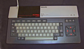
My first computer was one of these home computers: I had an MSX (a VG8020 by Philips).

Had a lot of fun with this MSX. Writing all kinds of little programs initially in the BASIC programming language, later on directly in z80 assembly code.
Around that time the movie War Games was in the cinemas. It featured a large computer called WOPR. WOPR was a grey box with lots of red lights blinking in interesting patterns. Unfortunately my MSX did not do that.
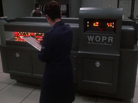
A week or two back I suddenly realized that I could add these so called blinken lights myself! So I sat down and started experimenting.
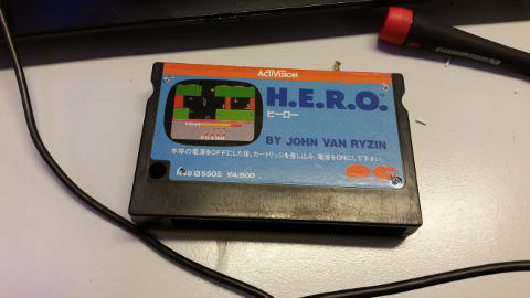
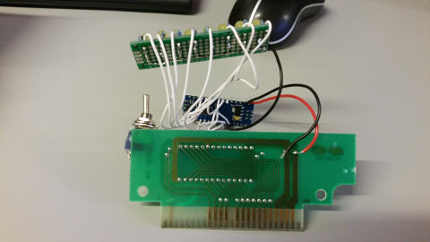
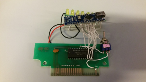
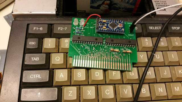
The cartridge port of the MSX is connected directly to the address- and databus of the MSX (please correct me if I'm wrong). So I thought it would be the easiest to solder a couple of LEDs directly on there. I'm not very transistor-happy so I took an Arduino Nano as a buffer. Using an Arduino inbetween has the extra benefit that I could do some processing before toggling the LEDs; that proved to be a wise decision (see late on). I could've cut a pcb to fit in that slot, instead I took an existing game cartridge:
On to the software. My initial Arduino "sketch" (software for Arduinos are called sketches) would read all 8 pins in a tight loop and then toggle the LEDs depending on the pin-states. This worked a bit: the leds switched very fast between 0 and 1, too fast for my eyes to see the difference between on and off. A bit of experimenting later I found that toggling them 24 times per second is too slow and 50 times per second is almost perfect.
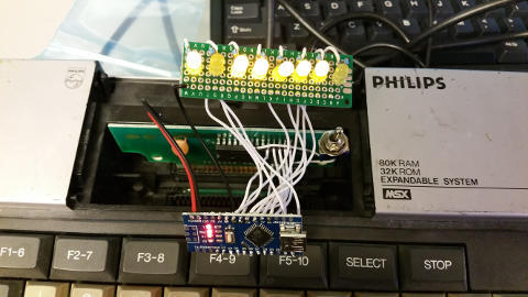
I inserted the cartridge and found it works very well!
Arduino sketch: MSXBlinkenLights.ino
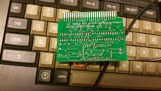
backside
front
inserted
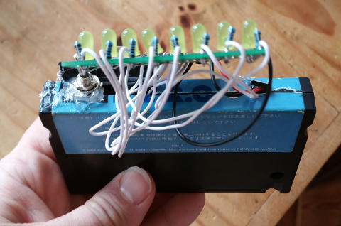
backside, closed
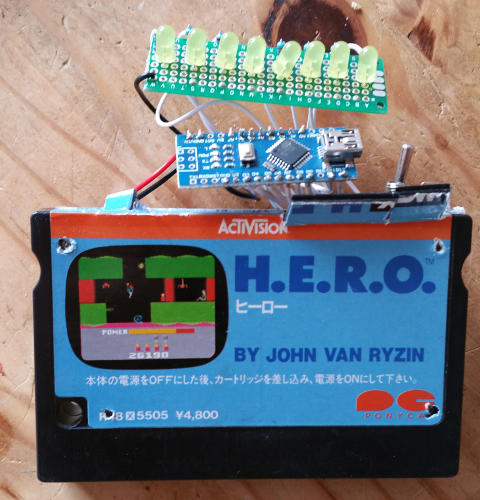
front, closed
top, closed
Youtube videos (recorded at RevSpace):
Room for improvement: it may be that the address bus gives more interesting light-patterns. One could then use e.g. an Adafruit i2c 24-channel led driver so that only pin 0, 1 (for serial comms) and pin a4/a5 are for leds and pin 2-13 and a0-a3 can be used for input-signals.
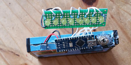
New version!
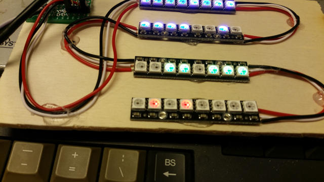
This version uses a neat PCB (own design, only 1 patch required :-]), an Arduino Pro Mini, MCP23017 ics and 4 Adafruit NeoPixel-bars. The MCP23017 modules are used to read the status of the 16 address lines, 8 bits for the data lines and then another 8 for control signals. The MCP23017 are connected over i2c to the Arduino. The NeoPixel bars use relatively a lot of power so they use a seperate power-connector (the MSX can deliver 350mA from what I've heard).
Youtube video (recorded at RevSpace):
For contact info, see this page.

numerus visitantium: MDLXXXI